

Products
0102030405
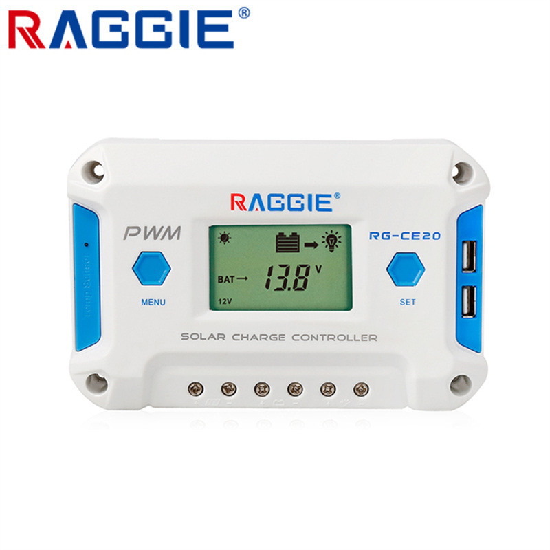
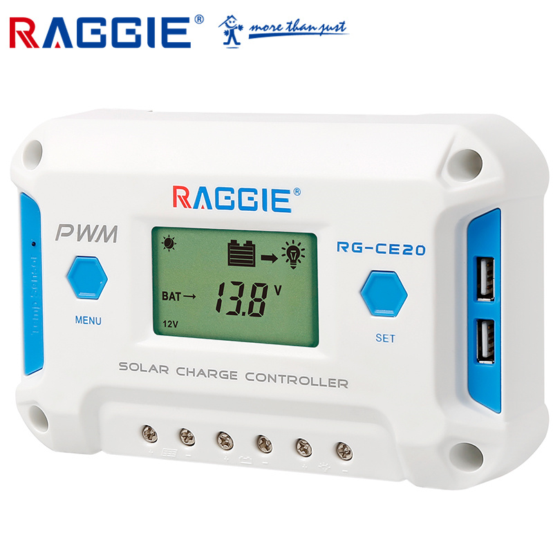
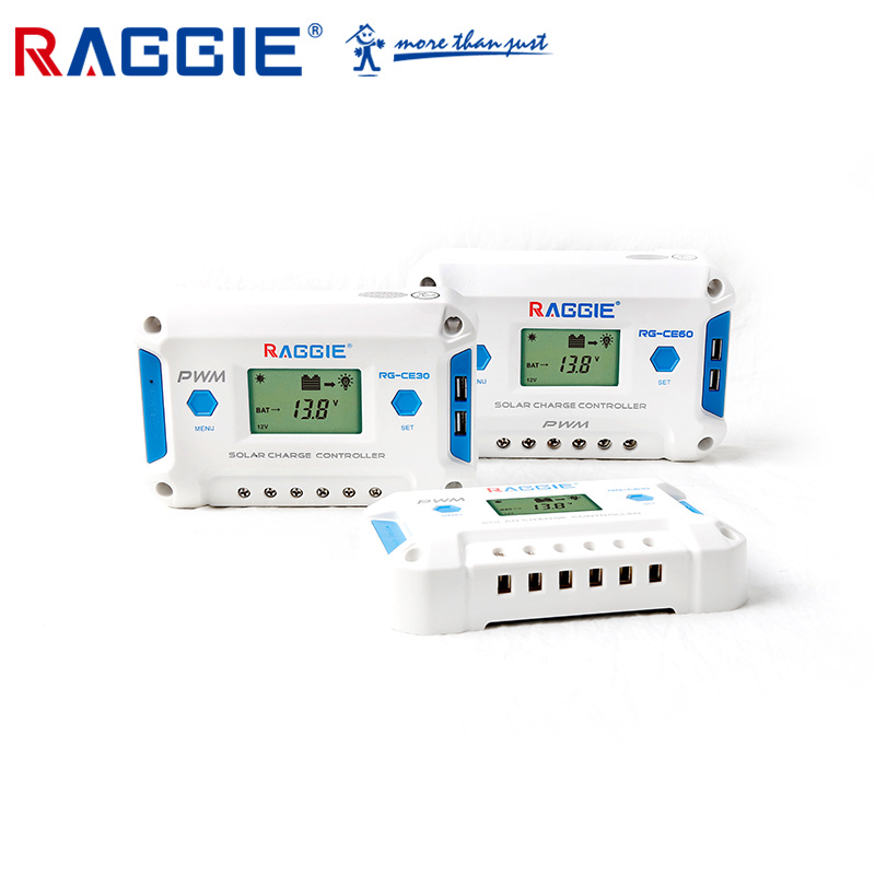
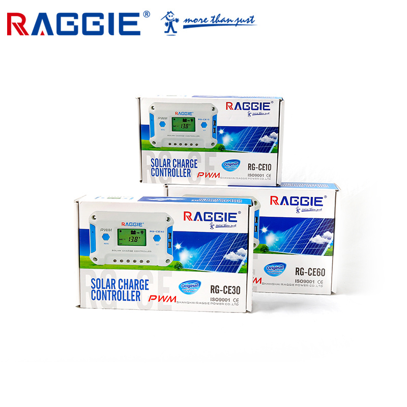
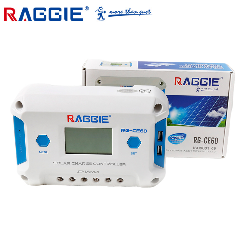
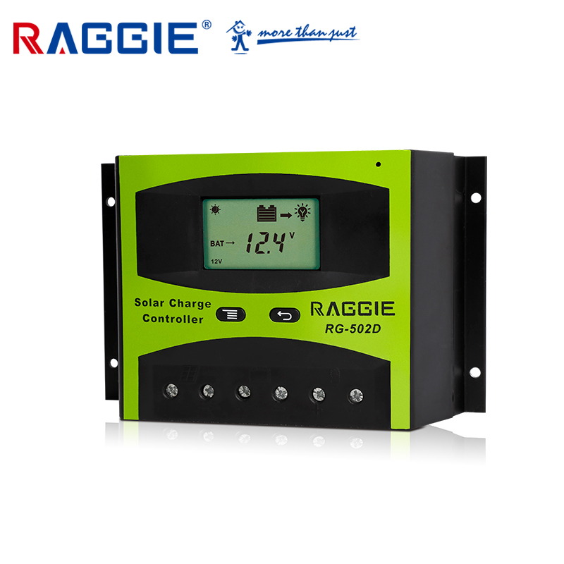
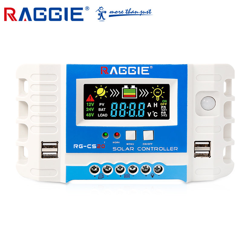
10A 20A 30A 40A 50A Solar Controller
Product Features
* Humanized LCD display with double button operation
* High efficiency intelligent PWM3-stage charging
* The timer can be resetfor street light at night
* The load control mode can be selected
* Accurate temperature compensation
* 12V/24Vor 12V/24V/48VAuto work
* Programmabletechnical data
* Over dischargeprotection
* Over charge protection
* Over voltage protection
* Short circuit protection
* Over load protection
* Auto correcting the charging and dischargingvoltage improving the battery lifetime * Polarity reverseprotection
* SolarPanels,Battery,Solarcharge controller Positive paralleled
* High quality STchips assuredlong life span
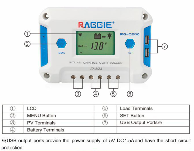
* Double USB designLithium battery support optional
Specifications
Item |
RG-CE10A |
RG-CE20A |
RG-CE30A |
RG-CE50A |
RG-CE60A |
Current |
10A |
20A |
30A |
50A |
60A |
Input voltage |
55V |
||||
Battery voltage |
12/24V auto |
||||
self comsuption |
≦12ma |
||||
battery type |
USR(default)/sealed/gel/flooded |
||||
LVD |
11Vadjustable 9~12V(24V*2,48V*4) |
||||
LVR |
12.6Vadjustable 11~13.5V(24V*2,48V*4) |
||||
Float voltage |
13.8Vadjustable 13~15V(24V*2,48V*4) |
||||
Boost charging |
14.4V(24V*2,48V*4),<12V start boost charging 2 hours |
||||
OVP volt |
16.5V overv oltage protection(24V*2,48V*4) |
||||
Reverse |
with reverse connection protection |
||||
Charging circuit drop≦0.25V | |||||
Discharging circuit drop≦0.12V | |||||
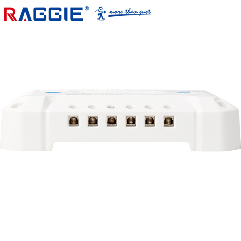
How to connect?
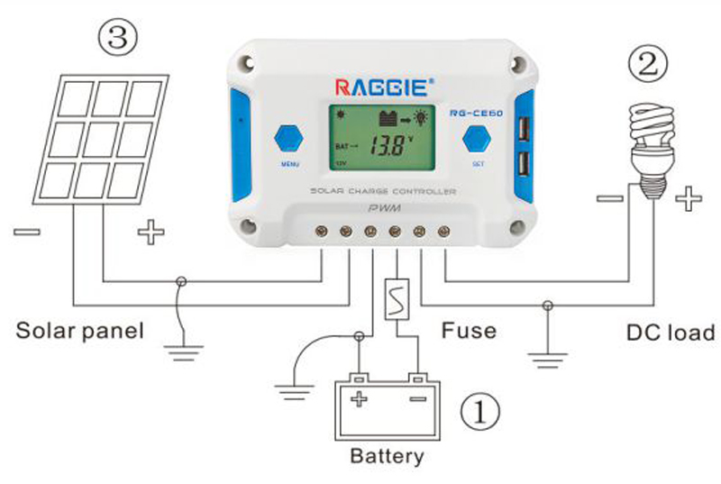
(1)Connect components to the charge controller in the sequence as shown above and pay much attention to the "+" and "-". Please don't insert the fuse or turn on the breaker during the installation. When disconnecting the system, the order will be reserved
(2)After power on the controller, check the LCD on. Otherwise please refer to chapter6.Always connect the battery first, in order to allow the controller to recognize the system voltage
(3)The battery fuse should be installed as close to battery as possible. The suggested distance is within 150mm.
(4)This series is a positive ground controller. Any positive connection of solar, load or battery can be earth grounded as required.
Controller Connection1)
All terminals are in tight status after factory, in order to well connected, pleaseloose all terminalsat first.
2)The following order of connection please do not free change, or cause system voltage recognition fault.
3) As figure, first connected the battery to controller correct poles, in order to avoid short circuit, please screw the cable of battery to the controller in advance, then connected to battery poles secondly. If your connection is correct, the LCD displaying will show battery voltage and other technical data, if LCDno indicate, pleasecheck the fault reason. The length of cable between battery and controller as shorter as possible. Suggest30cmto 100cm.