Encyclopedia introduction to solar inverters
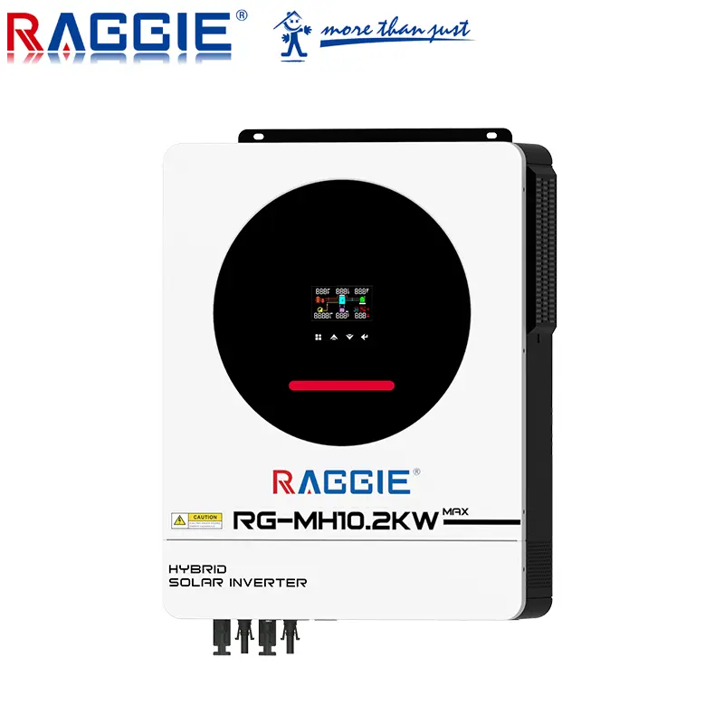
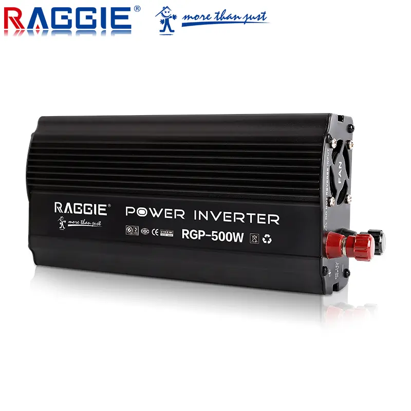
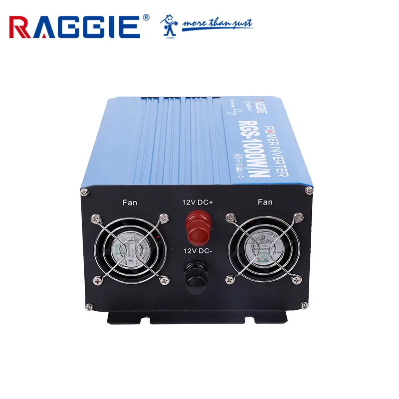
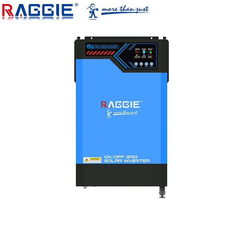
Inverter, also known as power regulator and power regulator, is an essential part of the photovoltaic system. The main function of the photovoltaic inverter is to convert the DC power generated by the solar panels into AC power used by home appliances. All the electricity generated by the solar panels must be processed by the inverter before it can be output to the outside world. [1] Through the full-bridge circuit, the SPWM processor is generally used to undergo modulation, filtering, voltage boosting, etc. to obtain sinusoidal AC power that matches the lighting load frequency, rated voltage, etc. for system end users. With an inverter, a DC battery can be used to provide AC power to appliances.
Introduction:
The solar AC power generation system is composed of solar panels, charge controller, inverter and battery; the solar DC power generation system does not include inverter. The process of converting AC power into DC power is called rectification, the circuit that completes the rectification function is called a rectifier circuit, and the device that implements the rectification process is called a rectifier device or rectifier. Correspondingly, the process of converting DC power into AC power is called inverter, the circuit that completes the inverter function is called an inverter circuit, and the device that implements the inverter process is called inverter equipment or inverter.
The core of the inverter device is the inverter switch circuit, referred to as the inverter circuit. This circuit completes the inverter function by turning on and off the power electronic switch. The switching of power electronic switching devices requires certain driving pulses, and these pulses may be adjusted by changing a voltage signal. The circuit that generates and regulates pulses is often called a control circuit or control loop. The basic structure of the inverter device includes, in addition to the above-mentioned inverter circuit and control circuit, a protection circuit, an output circuit, an input circuit, an output circuit, etc.
Features:
Due to the diversity of buildings, it will inevitably lead to the diversity of solar panel installations. In order to maximize the conversion efficiency of solar energy while taking into account the beautiful appearance of the building, this requires the diversification of our inverters to achieve the best way of solar energy. Convert.
Centralized inversion
Centralized inverter is generally used in systems of large photovoltaic power stations (>10kW). Many parallel photovoltaic strings are connected to the DC input of the same centralized inverter. Generally, three-phase IGBT power modules are used for high power. The smaller ones use field effect transistors and use DSP conversion controllers to improve the quality of the generated power so that it is very close to a sine wave current. The biggest feature is the high power and low cost of the system. However, the efficiency and electrical production capacity of the entire photovoltaic system are affected by the matching of photovoltaic strings and partial shading. At the same time, the power generation reliability of the entire photovoltaic system is affected by the poor working status of a certain photovoltaic unit group. The latest research directions are the use of space vector modulation control and the development of new inverter topology connections to obtain high efficiency under partial load conditions. On the SolarMax centralized inverter, a photovoltaic array interface box can be attached to monitor each string of photovoltaic sail panels. If one of the strings is not working properly, the system will The information is transmitted to the remote controller, and this string can be stopped through remote control, so that the failure of one photovoltaic string will not reduce or affect the work and energy output of the entire photovoltaic system.
String inverter
String inverters have become the most popular inverters in the international market. The string inverter is based on the modular concept. Each photovoltaic string (1kW-5kW) passes through an inverter, has maximum power peak tracking at the DC end, and is connected in parallel to the grid at the AC end. Many large photovoltaic power plants use string inverters. The advantage is that it is not affected by module differences and shadows between strings, and at the same time reduces the optimal operating point of photovoltaic modules.
Mismatch with the inverter, thereby increasing power generation. These technical advantages not only reduce system costs, but also increase system reliability. At the same time, the concept of "master-slave" is introduced between strings, so that when the power of a single string in the system cannot make a single inverter work, several groups of photovoltaic strings can be connected together to allow one or several of them to work. , thereby producing more electrical energy. The latest concept is that several inverters form a "team" with each other to replace the "master-slave" concept, making the system more reliable.
Multiple string inverter
Multi-string inverter takes the advantages of centralized inverter and string inverter, avoids their disadvantages, and can be applied to photovoltaic power stations with several kilowatts. In the multi-string inverter, different individual power peak tracking and DC-to-DC converters are included. The DC is converted into AC power through a common DC-to-AC inverter and connected to the grid. Different ratings of photovoltaic strings (e.g. different rated power, different number of modules per string, different manufacturers of modules, etc.), different sizes or different technologies of photovoltaic modules, different orientations of the strings (e.g. : east, south and west), different tilt angles or shading, can be connected to a common inverter, with each string operating at their respective maximum power peak. At the same time, the length of the DC cable is reduced, minimizing the shadowing effect between strings and the loss caused by differences between strings.
Component inverter
The module inverter connects each photovoltaic module to an inverter, and each module has an independent maximum power peak tracking, so that the module and the inverter cooperate better. Usually used in 50W to 400W photovoltaic power stations, the total efficiency is lower than that of string inverters. Since they are connected in parallel at the AC side, this increases the complexity of the wiring on the AC side and makes maintenance difficult. Another thing that needs to be solved is how to connect to the grid more effectively. The simple way is to connect to the grid directly through ordinary AC sockets, which can reduce costs and equipment installation, but often the safety standards of the power grid in various places may not allow it. In doing so, the power company may object to the direct connection of the generating device to an ordinary household socket. Another safety-related factor is whether an isolation transformer (high frequency or low frequency) is required or whether a transformerless inverter is allowed. This inverter is most widely used in glass curtain walls.
Solar Inverter Efficiency
The efficiency of solar inverters refers to the growing market for solar inverters (photovoltaic inverters) due to the demand for renewable energy. And these inverters require extremely high efficiency and reliability. The power circuits used in these inverters are examined and the best choices for switching and rectifier devices are recommended. The general structure of a photovoltaic inverter is shown in Figure 1. There are three different inverters to choose from. Sunlight shines on solar modules connected in series, and each module contains a set of solar cell units connected in series. The direct current (DC) voltage generated by solar modules is on the order of several hundred volts, depending on the lighting conditions of the module array, the temperature of the cells and the number of modules connected in series.
The primary function of this type of inverter is to convert the input DC voltage into a stable value. This function is implemented through a boost converter and requires a boost switch and a boost diode. In the first architecture, the boost stage is followed by an isolated full-bridge converter. The purpose of the full bridge transformer is to provide isolation. The second full-bridge converter on the output is used to convert the DC from the first-stage full-bridge converter into alternating current (AC) voltage. Its output is filtered before being connected to the AC grid network via an additional double-contact relay switch, in order to provide safe isolation in the event of a fault and isolation from the supply grid at night. The second structure is a non-isolated scheme. Among them, the AC voltage is directly generated by the DC voltage output by the boost stage. The third structure uses an innovative topology of power switches and power diodes to integrate the functions of the boost and AC generation parts in a dedicated topology, making the inverter as efficient as possible despite the very low conversion efficiency of the solar panel. Close to 100% but very important.In Germany, a 3kW series module installed on a south-facing roof is expected to generate 2550 kWh per year. If the inverter efficiency is increased from 95% to 96%, an additional 25kWh of electricity can be generated each year. The cost of using additional solar modules to generate this 25kWh is equivalent to adding an inverter. Since increasing efficiency from 95% to 96% will not double the cost of the inverter, investing in a more efficient inverter is an inevitable choice. For emerging designs, increasing inverter efficiency in the most cost-effective manner is a key design criterion. As for the reliability and cost of the inverter, they are two other design criteria. Higher efficiency reduces temperature fluctuations over the load cycle, thereby improving reliability, so these guidelines are actually related. The use of modules will also increase reliability.
Boost switch and diode
All topologies shown require fast switching power switches. The boost stage and full-bridge conversion stage require fast switching diodes. In addition, switches optimized for low frequency (100Hz) switching are also useful for these topologies. For any given silicon technology, switches optimized for fast switching will have higher conduction losses than switches optimized for low-frequency switching applications.
The boost stage is generally designed as a continuous current mode converter. Depending on the number of solar modules in the array used in the inverter, you can choose whether to use 600V or 1200V devices. Two choices for power switches are MOSFETs and IGBTs. Generally speaking, MOSFETs can operate at higher switching frequencies than IGBTs. In addition, the influence of the body diode must always be taken into account: in the case of the boost stage this is not a problem since the body diode does not conduct in normal operating mode. MOSFET conduction losses can be calculated from the on-resistance RDS(ON), which is proportional to the effective die area for a given MOSFET family. When the rated voltage changes from 600V to 1200V, the conduction losses of the MOSFET will increase greatly. Therefore, even if the rated RDS(ON) is equivalent, the 1200V MOSFET is not available or the price is too high.
For boost switches rated at 600V, superjunction MOSFETs can be used. For high-frequency switching applications, this technology has the best conduction losses. MOSFETs with RDS(ON) values below 100 milliohms in TO-220 packages and MOSFETs with RDS(ON) values below 50 milliohms in TO-247 packages. For solar inverters requiring 1200V power switching, IGBT is the appropriate choice. More advanced IGBT technologies, such as NPT Trench and NPT Field Stop, are optimized for reducing conduction losses, but at the expense of higher switching losses, which makes them less suitable for boost applications at high frequencies.
Based on the old NPT planar technology, a device FGL40N120AND was developed that can improve the efficiency of the boost circuit with high switching frequency. It has an EOFF of 43uJ/A. Compared with the more advanced technology devices, the EOFF is 80uJ/A, but it needs to be obtained This kind of performance is very difficult. The disadvantage of the FGL40N120AND device is that the saturation voltage drop VCE(SAT) (3.0V vs. 2.1V at 125ºC) is high, but its low switching losses at high boost switching frequencies more than make up for this. The device also integrates an anti-parallel diode. Under normal boost operation, this diode will not conduct. However, during start-up or during transient conditions, it is possible for the boost circuit to be driven into active mode, in which case the anti-parallel diode will conduct. Since the IGBT itself does not have an inherent body diode, this co-packaged diode is required to ensure reliable operation. For boost diodes, fast recovery diodes such as Stealth™ or carbon silicon diodes are required.Carbon-silicon diodes have very low forward voltage and losses. When selecting a boost diode, the effect of reverse recovery current (or junction capacitance of a carbon-silicon diode) on the boost switch must be considered, as this will result in additional losses. Here, the newly launched Stealth II diode FFP08S60S can provide higher performance. When VDD=390V, ID=8A, di/dt=200A/us, and case temperature is 100ºC, the calculated switching loss is lower than the FFP08S60S parameter of 205mJ. Using the ISL9R860P2 Stealth diode, this value reaches 225mJ. Therefore, this also improves the efficiency of the inverter at high switching frequencies.
Bridge switches and diodes
After MOSFET full-bridge filtering, the output bridge generates a 50Hz sinusoidal voltage and current signal. A common implementation is to use a standard full-bridge architecture (Figure 2). In the figure, if the switches on the upper left and lower right are turned on, a positive voltage is loaded between the left and right terminals; if the switches on the upper right and lower left are turned on, a negative voltage is loaded between the left and right terminals. For this application, only one switch is on during a certain period of time. One switch can be switched to PWM high frequency and the other switch to low frequency 50Hz. Since the bootstrap circuit relies on the conversion of low-end devices, the low-end devices are switched to PWM high frequency, while the high-end devices are switched to 50Hz low frequency. This application uses a 600V power switch, so the 600V superjunction MOSFET is very suitable for this high-speed switching device. Because these switching devices will withstand the full reverse recovery current of other devices when the switch is on, fast recovery superjunction devices such as the 600V FCH47N60F are ideal choices. Its RDS(ON) is 73 milliohms, and its conduction loss is very low compared to other similar fast recovery devices. When this device converts at 50Hz, there is no need to use the fast recovery feature. These devices have excellent dv/dt and di/dt characteristics, which improves system reliability compared to standard superjunction MOSFETs.
Another option worth exploring is the use of the FGH30N60LSD device. It is a 30A/600V IGBT with a saturation voltage VCE(SAT) of only 1.1V. Its turn-off loss EOFF is very high, reaching 10mJ, so it is only suitable for low-frequency conversion. A 50 milliohm MOSFET has an on-resistance RDS(ON) of 100 milliohms at operating temperature. Therefore, at 11A, it has the same VDS as the VCE(SAT) of the IGBT. Since this IGBT is based on older breakdown technology, VCE(SAT) does not change much with temperature. This IGBT therefore reduces the overall losses in the output bridge, thereby increasing the overall efficiency of the inverter. The fact that the FGH30N60LSD IGBT switches from one power conversion technology to another dedicated topology every half cycle is also useful. IGBTs are used here as topological switches. For faster switching, conventional and fast recovery superjunction devices are used. For 1200V dedicated topology and full-bridge structure, the aforementioned FGL40N120AND is a switch that is very suitable for new high-frequency solar inverters. When specialized technologies require diodes, Stealth II, Hyperfast™ II diodes and carbon-silicon diodes are great solutions.
function:
The inverter not only has the function of DC to AC conversion, but also has the function of maximizing the performance of solar cells and the function of system fault protection. In summary, there are automatic running and shutdown functions, maximum power tracking control function, independent operation prevention function (for grid-connected systems), automatic voltage adjustment function (for grid-connected systems), DC detection function (for grid-connected systems), and DC ground detection. Function (for grid-connected systems). Here is a brief introduction to the automatic running and shutdown functions and the maximum power tracking control function.
Automatic operation and shutdown function: After sunrise in the morning, the intensity of solar radiation gradually increases, and the output of the solar cell also increases. When the output power required for the inverter operation is reached, the inverter automatically starts running. After entering operation, the inverter will monitor the output of the solar cell modules at all times. As long as the output power of the solar cell modules is greater than the output power required for the inverter task, the inverter will continue to operate; it will stop until sunset, even if The inverter can also operate on rainy days. When the solar module output becomes smaller and the inverter output approaches 0, the inverter enters a standby state.
Maximum power tracking control function: The output of the solar cell module changes with the intensity of solar radiation and the temperature of the solar cell module itself (chip temperature). In addition, because solar cell modules have the characteristic that voltage decreases as current increases, there is an optimal operating point that can obtain maximum power. The intensity of solar radiation is changing, and obviously the optimal working point is also changing. Related to these changes, the working point of the solar cell module is always kept at the maximum power point, and the system always obtains the maximum power output from the solar cell module. This kind of control is maximum power tracking control. The biggest feature of inverters used in solar power generation systems is that they include the maximum power point tracking (MPPT) function.
type
Application scope classification
(1) Ordinary inverter
DC 12V or 24V input, AC 220V, 50Hz output, power from 75W to 5000W, some models have AC and DC conversion, that is, UPS function.
(2) Inverter/charger all-in-one machine
In this type of inverter, users can use various forms of power to power AC loads: when there is AC power, the AC power is used to power the load through the inverter, or to charge the battery; when there is no AC power, the battery is used to power the AC load. . It can be used in conjunction with various power sources: batteries, generators, solar panels and wind turbines.
(3) Special inverter for post and telecommunications
Provide high-quality 48V inverters for postal and telecommunications services. The products are of good quality, high reliability, modular (module is 1KW) inverters, and have N+1 redundancy function and can be expanded (power from 2KW to 20KW). ).
(4) Special inverter for aviation and military
This type of inverter has a 28Vdc input and can provide the following AC outputs: 26Vac, 115Vac, 230Vac. Its output frequency can be: 50Hz, 60Hz and 400Hz, and the output power ranges from 30VA to 3500VA. There are also DC-DC converters and frequency converters dedicated to aviation.
Output waveform classification
(1) Square wave inverter
The AC voltage waveform output by the square wave inverter is a square wave. The inverter circuits used by this type of inverter are not exactly the same, but the common feature is that the circuit is relatively simple and the number of power switch tubes used is small. The design power is generally between one hundred watts and one kilowatt. The advantages of square wave inverter are: simple circuit, cheap price and easy maintenance. The disadvantage is that the square wave voltage contains a large number of high-order harmonics, which will produce additional losses in load appliances with iron core inductors or transformers, causing interference to radios and some communication equipment. In addition, this type of inverter has shortcomings such as insufficient voltage regulation range, incomplete protection function, and relatively high noise.
(2) Step wave inverter
The AC voltage waveform output by this type of inverter is a step wave. There are many different lines for the inverter to realize step wave output, and the number of steps in the output waveform varies greatly. The advantage of the step wave inverter is that the output waveform is significantly improved compared to the square wave, and the high-order harmonic content is reduced. When the steps reach more than 17, the output waveform can achieve a quasi-sinusoidal wave. When transformerless output is used, the overall efficiency is very high. The disadvantage is that the ladder wave superposition circuit uses a lot of power switch tubes, and some of the circuit forms require multiple sets of DC power inputs. This brings trouble to the grouping and wiring of solar cell arrays and the balanced charging of batteries. In addition, the staircase wave voltage still has some high-frequency interference to radios and some communication equipment.
Sine wave inverter
The AC voltage waveform output by the sine wave inverter is a sine wave. The advantages of the sine wave inverter are that it has good output waveform, very low distortion, little interference to radios and equipment, and low noise. In addition, it has complete protection functions and high overall efficiency. The disadvantages are: the circuit is relatively complex, requires high maintenance technology, and is expensive.
The classification of the above three types of inverters is helpful for designers and users of photovoltaic systems and wind power systems to identify and select inverters. In fact, inverters with the same waveform still have great differences in circuit principles, devices used, control methods, etc.
Other classification methods
1. According to the frequency of output AC power, it can be divided into power frequency inverter, medium frequency inverter and high frequency inverter. The frequency of power frequency inverter is 50 to 60Hz; the frequency of medium frequency inverter is generally 400Hz to more than ten kHz; the frequency of high frequency inverter is generally more than ten kHz to MHz.
2. According to the number of phases output by the inverter, it can be divided into single-phase inverter, three-phase inverter and multi-phase inverter.
3. According to the destination of the inverter’s output power, it can be divided into active inverter and passive inverter. Any inverter that transmits the electric energy output by the inverter to the industrial power grid is called an active inverter; any inverter that transmits the electric energy output by the inverter to some electrical load is called a passive inverter. device.
4. According to the form of the inverter main circuit, it can be divided into single-ended inverter, push-pull inverter, half-bridge inverter and full-bridge inverter.
5. According to the type of main switching device of the inverter, it can be divided into thyristor inverter, transistor inverter, field effect inverter and insulated gate bipolar transistor (IGBT) inverter. It can be divided into two categories: "semi-controlled" inverter and "fully controlled" inverter. The former does not have the ability to self-turn off, and the component loses its control function after it is turned on, so it is called "semi-controlled" and ordinary thyristors fall into this category; the latter has the ability to self-turn off, that is, there is no device The on and off can be controlled by the control electrode, so it is called "fully controlled type". Power field effect transistors and insulated gate bi-power transistors (IGBT) all belong to this category.
6. According to DC power supply, it can be divided into voltage source inverter (VSI) and current source inverter (CSI). In the former, the DC voltage is nearly constant, and the output voltage is an alternating square wave; in the latter, the DC current is nearly constant, and the output current is an alternating square wave.
7. According to the inverter control method, it can be divided into frequency modulation (PFM) inverter and pulse width modulation (PWM) inverter.
8. According to the working mode of the inverter switching circuit, it can be divided into resonant inverter, fixed frequency hard switching inverter and fixed frequency soft switching inverter.
9. According to the commutation method of the inverter, it can be divided into load-commutated inverter and self-commutated inverter.
Performance parameters:
There are many parameters and technical conditions that describe the performance of an inverter. Here we only give a brief explanation of the technical parameters commonly used when evaluating inverters.
1. Environmental conditions for the use of the inverter. Normal use conditions of the inverter: the altitude does not exceed 1000m, and the air temperature is 0~+40℃.
2. DC input power supply conditions, input DC voltage fluctuation range: ±15% of the rated voltage value of the battery pack.
3. Rated output voltage, within the specified allowable fluctuation range of the input DC voltage, it represents the rated voltage value that the inverter should be able to output. The stable accuracy of the output rated voltage value generally has the following provisions:
(1) During steady-state operation, the voltage fluctuation range should be limited, for example, its deviation should not exceed ±3% or ±5% of the rated value.
(2) In dynamic situations where the load changes suddenly or is affected by other interference factors, the output voltage deviation should not exceed ±8% or ±10% of the rated value.
4. Rated output frequency, the frequency of the inverter output AC voltage should be a relatively stable value, usually the power frequency of 50Hz. The deviation should be within ±1% under normal working conditions.
5. Rated output current (or rated output capacity) indicates the rated output current of the inverter within the specified load power factor range. Some inverter products give rated output capacity, expressed in VA or kVA. The rated capacity of the inverter is when the output power factor is 1 (that is, purely resistive load), the rated output voltage is the product of the rated output current.
6. Rated output efficiency. The efficiency of the inverter is the ratio of its output power to the input power under specified working conditions, expressed in %. The efficiency of the inverter at rated output capacity is full load efficiency, and the efficiency at 10% of rated output capacity is low load efficiency.
7. The maximum harmonic content of the inverter. For a sine wave inverter, under resistive load, the maximum harmonic content of the output voltage should be ≤10%.
8. The overload capacity of the inverter refers to the ability of the inverter to output more than the rated current value in a short period of time under specified conditions. The overload capacity of the inverter should meet certain requirements under the specified load power factor.
9. The efficiency of the inverter is the ratio of the inverter output active power to the input active power (or DC power) under the rated output voltage, output current and specified load power factor.
10. Load power factor represents the inverter’s ability to carry inductive or capacitive loads. Under sine wave conditions, the load power factor is 0.7~0.9 (lag), and the rated value is 0.9.
11. Load asymmetry. Under a 10% asymmetric load, the asymmetry of the output voltage of a fixed-frequency three-phase inverter should be ≤10%.
12. Output voltage imbalance. Under normal operating conditions, the three-phase voltage imbalance (ratio of reverse sequence component to positive sequence component) output by the inverter should not exceed a specified value, generally expressed in %, such as 5 % or 8%.
13. Starting characteristics: Under normal operating conditions, the inverter should be able to start normally 5 times in a row under full load and no-load operating conditions.
14. Protection functions, the inverter should be set up: short circuit protection, overcurrent protection, overtemperature protection, overvoltage protection, undervoltage protection and phase loss protection. Among them, overvoltage protection means that for inverters without voltage stabilization measures, there should be output overvoltage protection measures to protect the negative terminal from damage by output overvoltage. Overcurrent protection refers to the overcurrent protection of the inverter, which should be able to ensure timely action when the load is short-circuited or the current exceeds the allowable value to protect it from damage by surge current.
15. Interference and anti-interference, the inverter should be able to withstand electromagnetic interference in the general environment under specified normal working conditions. The anti-interference performance and electromagnetic compatibility of the inverter should comply with relevant standards.
16. Inverters that are not frequently operated, monitored and maintained should be ≤95db; inverters that are frequently operated, monitored and maintained should be ≤80db.
17. Display, the inverter should be equipped with data display of parameters such as AC output voltage, output current and output frequency, and signal display of input live, energized and fault status.
18. Communication function. The remote communication function allows users to check the machine's operating status and stored data without going to the site.
19. The waveform distortion of the output voltage. When the inverter output voltage is sinusoidal, the maximum allowable waveform distortion (or harmonic content) should be specified. Usually expressed as the total waveform distortion of the output voltage, its value should not exceed 5% (10% is allowed for single-phase output).
20. Starting characteristics, which characterize the inverter's ability to start with load and its performance during dynamic operation. The inverter should ensure reliable starting under rated load.
21. Noise. Transformers, filter inductors, electromagnetic switches, fans and other components in power electronic equipment all produce noise. When the inverter is operating normally, its noise should not exceed 80dB, and the noise of a small inverter should not exceed 65dB.
Battery characteristics:
PV battery
To develop a solar inverter system, it is important to first understand the different characteristics of solar cells (PV cells). Rp and Rs are parasitic resistances, which are infinite and zero respectively under ideal circumstances.
Light intensity and temperature can significantly affect the operating characteristics of PV cells. The current is proportional to the light intensity, but changes in light have little effect on the operating voltage. However, the operating voltage is affected by temperature. An increase in battery temperature reduces the operating voltage but has little effect on the current generated. The figure below illustrates the effects of temperature and light on PV modules.
Changes in light intensity have a greater impact on battery output power than changes in temperature. This is true for all commonly used PV materials. An important consequence of the combination of these two effects is that the power of a PV cell decreases with decreasing light intensity and/or increasing temperature.
Maximum power point (MPP)
Solar cells can operate over a wide range of voltages and currents. The MPP is determined by continuously increasing the resistive load on the illuminated cell from zero (short circuit event) to a very high value (open circuit event). MPP is the operating point at which V x I reaches its maximum value and at this illumination intensity Maximum power can be achieved. The output power when a short circuit (PV voltage equals zero) or open circuit (PV current equals zero) event occurs is zero.
High-quality monocrystalline silicon solar cells produce an open circuit voltage of 0.60 volts at a temperature of 25°C. With full sunlight and an air temperature of 25°C, the temperature of a given cell may be close to 45°C, which will reduce the open circuit voltage to about 0.55V. As the temperature increases, the open circuit voltage continues to decrease until the PV Module short circuit.
Maximum power at a battery temperature of 45°C is typically produced at 80% open circuit voltage and 90% short circuit current. The short-circuit current of the battery is almost proportional to the illumination, and the open-circuit voltage may only decrease by 10% when the illumination is reduced by 80%. Lower-quality batteries will reduce the voltage faster when the current increases, thereby reducing the available power. The output dropped from 70% to 50%, or even only 25%.
The solar microinverter must ensure that the PV modules are operating at the MPP at any given time so that maximum energy can be obtained from the PV modules. This can be achieved using a maximum power point control loop, also known as a Maximum Power Point Tracker (MPPT). Achieving a high ratio of MPP tracking also requires that the PV output voltage ripple is small enough so that the PV current does not change too much when operating near the maximum power point.
The MPP voltage range of PV modules can usually be defined in the range of 25V to 45V, with a power generation of approximately 250W and an open circuit voltage below 50V.
Use and maintenance:
use
1. Connect and install the equipment strictly in accordance with the requirements of the inverter operation and maintenance instructions. During installation, you should carefully check: whether the wire diameter meets the requirements; whether the components and terminals are loose during transportation; whether the insulated parts are well insulated; whether the system's grounding meets the regulations.
2. The inverter should be operated and used strictly in accordance with the instructions for use and maintenance. In particular: before turning on the machine, pay attention to whether the input voltage is normal; during operation, pay attention to whether the sequence of turning on and off the machine is correct, and whether the indications of each meter and indicator light are normal.
3. Inverters generally have automatic protection for circuit breakage, overcurrent, overvoltage, overheating and other items, so when these phenomena occur, there is no need to shut down manually; the protection points of automatic protection are generally set at the factory, and no need to Adjust again.
4. There is high voltage in the inverter cabinet. Operators are generally not allowed to open the cabinet door, and the cabinet door should be locked at ordinary times.
5. When the room temperature exceeds 30°C, heat dissipation and cooling measures should be taken to prevent equipment failure and extend the service life of the equipment.
Maintenance and inspection
1. Regularly check whether the wiring of each part of the inverter is firm and whether there is any looseness. In particular, the fan, power module, input terminal, output terminal and grounding should be carefully checked.
2. Once the alarm shuts down, it is not allowed to start up immediately. The cause should be found out and repaired before starting up. The inspection should be carried out strictly in accordance with the steps specified in the inverter maintenance manual.
3. Operators must receive special training and be able to determine the causes of general faults and eliminate them, such as skillfully replacing fuses, components, and damaged circuit boards. Untrained personnel are not allowed to operate the equipment.
4. If an accident occurs that is difficult to eliminate or the cause of the accident is unclear, detailed records of the accident should be kept and the inverter manufacturer should be notified in a timely manner for resolution.


